Description
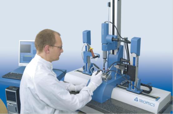
![]() The Opticentric is the leading and Most Comprehensive Line of Equipment for Optical Alignment, Centering, Cementing, Bonding and Alignment Turning.
The Opticentric is the leading and Most Comprehensive Line of Equipment for Optical Alignment, Centering, Cementing, Bonding and Alignment Turning.
Click here for the Opticentric Brochure
 According to ISO 10110 a centering error is present when the optical and the reference axis of a lens do not coincide, respectively these are different in position or direction. During the process of cementing, alignment and bonding of lenses in a mount, significant centering errors can result and add to the machining errors of a lens. Consequently, the requirements of a high performance optical system can only be fulfilled when all the production steps from the centering tolerance measurement to the assembly of the lens in a mount are planned and designed as an integrated concept.
The OptiCentric System also covers all the production steps from the centration measurement to the alignment, cementing and assembly of optics. The OptiCentric includes valuable tools for any application, from simple and affordable visual instruments to complex, fully automated and PC-controlled production and laboratory stations.
- OptiCentric® METRO – for metrology and comprehensive measurement of optical systems.
- OptiCentric® PRO – for production and assembly of objective lenses.
![]()
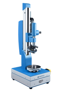
Measurement of Centration Errors of all Kinds of Lenses and Objective Lenses
OptiCentric® METRO instruments are designed to measure centering errors and other parameter of lenses and optical systems. All instruments of the METRO series can be used to carry out measurements using the reflection mode and/or transmission mode, an exception being the OptiCentric® SMART which only works in reflection mode.
OptiCentric® METRO is of modular design, so that the instruments are upgradeable and compatible with each other.
To make the selection of the suitable equipment easier, in a first step the main instrument parts are presented.
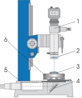
- Autocollimator with CCD-Camera
- Additional Achromat in X-,Y- adj.Mount
- Sample
- Mirror
- Collimator
- Lens rotation device
![]()
The OptiCentric® PRO line for production offers a range of fully automated cementing, bonding and alignment turning stations. The powerful products are fully automated and comply in the basic configuration with the OptiCentric® MOT 100. All sub assemblies like a glue dispenser or the motorized stepper are PC controlled.
Lens manufacturing not only includes glue bonding of a lens to a barrel, but also the centering and cementing of two lenses to a doublet. For this purpose TRIOPTICS has developed the OptiCentric® Cementing Station as a supplement to the TRIOPTICS OptiCentric System.
It includes a 2-axis x-y piezoelectric fine positioning stage and a lens specific grabber. The grabber does the precise positioning of the upper lens to the optimally centered position with respect to the lower lens.
The centering procedure relies on the proprietary TRIOPTICS MultiLens algorithm. It determines first the optical axis of the lower lens and calculates the target position for the top lens. The top lens is then pushed by the piezo driven grabber to the target position under control of the high resolution CCD autocollimator.
With this technology, doublets with centering accuracies below 1 micron can be achieved. Similar to the Bonding Station, the complete process is computer controlled. Driven by customer demands in the high volume market of plastic molded lenses the process has been optimized for throughput. The complete cementing cycle including UV curing and manual sample handling is performed within less than 10 seconds.
OptiCentric Bonding Station
The TRIOPTICS Automatic Bonding Station extends the capabilities of the OptiCentric System into automatic manufacturing processes of optical components and systems. Modern objective lenses rely more and more on glue bonded components which, besides the lower cost, save space and weight.
The OptiCentric Bonding Station includes all the devices necessary for the precise and automated centering and glue bonding of lenses into barrels and other optical subassemblies. A glue dispenser is mounted on a motorized x-z stepper motor stage for the automatic positioning of the dispenser tip to the gluing position.
The centering process is controlled by the OptiCentric System which relies on a high resolution CCD autocollimator and the precise sample rotation with an air bearing.
High-precision centering results better than 2.5 microns are typically achieved in 2 min processing time including UV curing time. The UV curing of the glue after lens alignment is enabled by a computer controlled UV light source and several light guide outlets.